| 01_Matlab | ||
| 02_Arduino | ||
| docs | ||
| Drivers | ||
| Inc | ||
| Src | ||
| .gitattributes | ||
| .gitignore | ||
| .travis.yml | ||
| LICENSE | ||
| Makefile | ||
| pinout.png | ||
| platformio.ini | ||
| README.md | ||
| startup_stm32f103xe.s | ||
| STM32F103RCTx_FLASH.ld | ||
hoverboard-firmware-hack-FOC
with Field Oriented Control (FOC)

 If you like this project, you can give me a cup of coffee. Thanks!
This repository implements Field Oriented Control (FOC) for stock hoverboards. Compared to the commutation method, this new FOC control method offers superior performance featuring:
- reduced noise and vibrations
- smooth torque output and improved motor efficiency. Thus, lower energy consumption
- field weakening to increase maximum speed range
This new firmware offers 3 control modes:
- VOLTAGE MODE: in this mode the controller applies a constant Voltage to the motors
- SPEED MODE: in this mode a closed-loop controller realizes the input target speed by rejecting any of the disturbance (resistive load) applied to the motor
- TORQUE MODE: in this mode the target torque set by the user is realized. This mode enables motor "freewheeling" when the torque target is "0".
NOTE: In all the modes, the controller features maximum motor speed and maximum motor current protection. This brings great advantages to fulfil the needs of many robotic applications while maintaining safe operation.
Firmware architecture
The main firmware architecture includes:
- Estimations: estimates the rotor position, angle and motor speed based on Hall sensors signal
- Diagnostics: implements error detection such as unconnected Hall sensor, motor blocked, MOSFET defective
- Control Manager: manages the transitions between control modes (Voltage, Speed, Torque)
- FOC Algorithm: implements the FOC strategy
- Control Type Manager: Manages the transition between Commutation, Sinusoidal, and FOC control type

The FOC algorithm architecture is illustrated in the figure below:

In this firmware 3 control types are available:
- Commutation
- SIN (Sinusoidal)
- FOC (Field Oriented Control)

Demo videos:
►Video: Commutation vs Advanced control (constant speed)
►Video: Commutation vs Advanced control (variable speed)
►Video: Reliable Serial Communication demo

General Notes
- The C code for the controller was auto-code generated using Matlab/Simulink from a model which I developed from scratch specifically for hoverboard control. For more details regarding the working principle of the controller please consult the Matlab/Simulink model.
- A webview was created, so Matlab/Simulink installation is not needed, unless you want to regenerate the code. The webview is an html page that can be opened with browsers like: Microsoft Internet Explorer or Microsoft Edge.
Field Weakening / Phase Advance
- By default the Field weakening is disabled. You can enable it in config.h file by setting the FIELD_WEAK_ENA = 1
- The Field Weakening is a linear interpolation from 0 to FIELD_WEAK_MAX or PHASE_ADV_MAX (depeding if FOC or SIN is selected, respectively)
- The Field Weakening starts engaging at FIELD_WEAK_LO and reaches the maximum value at FIELD_WEAK_HI
- The figure below shows different possible calibrations for Field Weakening / Phase Advance

- If you re-calibrate the Field Weakening please take all the safety measures! The motors can spin very fast!
Parameters
- All the calibratable motor parameters can be found in the 'BLDC_controller_data.c'. I provided you with an already calibrated controller, but if you feel like fine tuning it feel free to do so
- The parameters are represented in Fixed-point data type for a more efficient code execution
- For calibrating the fixed-point parameters use the Fixed-Point Viewer tool
- The parameters data Fixed-point types are given in the following table:

Diagnostics
Each motor is constantly monitored for errors. These errors are:
- Error 001: Hall sensor not connected
- Error 002: Hall sensor short circuit
- Error 004: Motor NOT able to spin (Possible causes: motor phase disconnected, MOSFET defective, operational Amplifier defective, motor blocked)
The error codes above are reported for each motor in the variables errCode_Left and errCode_Right for Left motor (long wired motor) and Right motor (short wired motor), respectively. In case of error, the motor power is reduced to 0, while an audible (fast beep) can be heard to notify the user.
Building
For building (and flashing) I recommend platform.io, plaformio.ini file included. Simply open the folder in the IDE of choice (vscode or Atom), and press the 'PlatformIO:Build' or the 'PlatformIO:Upload' button (bottom left in vscode).
Additionally, you can also flash using the method described below in the Flashing Section.
Hardware
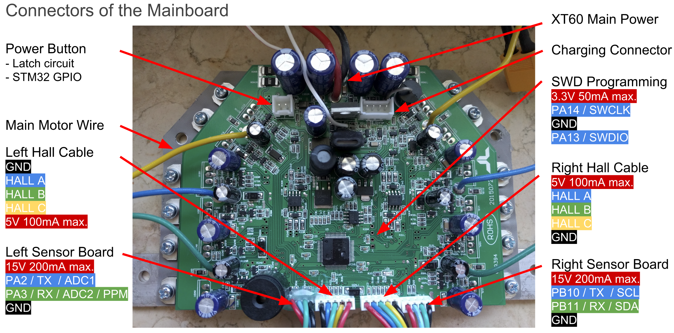
The original Hardware supports two 4-pin cables that originally were connected to the two sensor boards. They break out GND, 12/15V and USART2&3 of the Hoverboard mainboard. Both USART2 & 3 can be used for UART and I2C, PA2&3 can be used as 12bit ADCs.
The reverse-engineered schematics of the mainboard can be found here: http://vocke.tv/lib/exe/fetch.php?media=20150722_hoverboard_sch.pdf
Flashing
To build the firmware, just type "make". Make sure you have specified your gcc-arm-none-eabi binary location in the Makefile ("PREFIX = ...") (version 7 works, there is a version that does not!) (if the ons in linux repos do not work, use the official version: https://developer.arm.com/open-source/gnu-toolchain/gnu-rm/downloads). Right to the STM32, there is a debugging header with GND, 3V3, SWDIO and SWCLK. Connect GND, SWDIO and SWCLK to your SWD programmer, like the ST-Link found on many STM devboards.
Do not power the mainboard from the 3.3V of your programmer! This has already killed multiple mainboards.
Make sure you hold the powerbutton or connect a jumper to the power button pins while flashing the firmware, as the STM might release the power latch and switches itself off during flashing. Battery > 36V have to be connected while flashing.
To flash the STM32, use the ST-Flash utility (https://github.com/texane/stlink).
If you never flashed your mainboard before, the STM is probably locked. To unlock the flash, use the following OpenOCD command:
openocd -f interface/stlink-v2.cfg -f target/stm32f1x.cfg -c init -c "reset halt" -c "stm32f1x unlock 0"
If that does not work:
openocd -f interface/stlink-v2.cfg -f target/stm32f1x.cfg -c init -c "reset halt" -c "mww 0x40022004 0x45670123" -c "mww 0x40022004 0xCDEF89AB" -c "mww 0x40022008 0x45670123" -c "mww 0x40022008 0xCDEF89AB" -c "mww 0x40022010 0x220" -c "mww 0x40022010 0x260" -c "sleep 100" -c "mww 0x40022010 0x230" -c "mwh 0x1ffff800 0x5AA5" -c "sleep 1000" -c "mww 0x40022010 0x2220" -c "sleep 100" -c "mdw 0x40022010" -c "mdw 0x4002201c" -c "mdw 0x1ffff800" -c targets -c "halt" -c "stm32f1x unlock 0"
openocd -f interface/stlink-v2.cfg -f target/stm32f1x.cfg -c init -c "reset halt" -c "mww 0x40022004 0x45670123" -c "mww 0x40022004 0xCDEF89AB" -c "mww 0x40022008 0x45670123" -c "mww 0x40022008 0xCDEF89AB" -c targets -c "halt" -c "stm32f1x unlock 0"
Or use the Windows ST-Link utility.
Then you can simply flash the firmware:
st-flash --reset write build/hover.bin 0x8000000
or
openocd -f interface/stlink-v2.cfg -f target/stm32f1x.cfg -c flash "write_image erase build/hover.bin 0x8000000"
Troubleshooting
First, check that power is connected and voltage is >36V while flashing. If the board draws more than 100mA in idle, it's probably broken.
If the motors do something, but don't rotate smooth and quietly, try to use an alternative phase mapping. Usually, color-correct mapping (blue to blue, green to green, yellow to yellow) works fine. However, some hoverboards have a different layout then others, and this might be the reason your motor isn't spinning.
Nunchuck not working: Use the right one of the 2 types of nunchucks. Use i2c pullups.
Nunchuck or PPM working bad: The i2c bus and PPM signal are very sensitive to emv distortions of the motor controller. They get stronger the faster you are. Keep cables short, use shielded cable, use ferrits, stabilize voltage in nunchuck or reviever, add i2c pullups. To many errors leads to very high accelerations which triggers the protection board within the battery to shut everything down.
Most robust way for input is to use the ADC and potis. It works well even on 1m unshielded cable. Solder ~100k Ohm resistors between ADC-inputs and gnd directly on the mainboard. Use potis as pullups to 3.3V.
Examples
Have a look at the config.h in the Inc directory. That's where you configure to firmware to match your project. Currently supported: Wii Nunchuck, analog potentiometer and PPM-Sum signal from a RC remote. A good example of control via UART, eg. from an Arduino or raspberryPi, can be found here: https://github.com/p-h-a-i-l/hoverboard-firmware-hack
Acknowledgements
Last but not least, I would like to acknowledge and thank the following people:
- Original firmware: @NiklasFauth
- Github: @TomTinkering, @ced2c, @btsimonh, @lalalandrus, @p-h-a-i-l , @AntumArk, @juodumas
- ST Employee: cedric H
for the very useful discussions, code snippets, and good suggestions to make this work possbile.